Active Research Interests
| For anyone who might be
curious about the work I engage in outside of teaching,
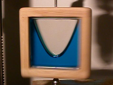
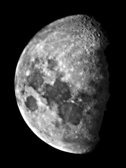
here is a little about that work. Over a decade ago I was visiting my undergraduate adviser, Dr. John Safko. He showed off a telescope mirror produced by spincasting a special epoxy. The mirror looked terrific and I fell in love with the idea of making such mirrors. I made a note to explore the idea when I had some extra time. The short version of this story is that a few years later Dr. Wally Scrivens asked me to join his research group which had produced the mirror I saw. I collaborated with Wally Scrivens (formally at USC and now with Milliken in Spartanburg) for several years and supervised part of the research of two of his Ph. D. students. The thrust of this work is the production of finished optical quality epoxy mirrors entirely by spincasting without any grinding or polishing. Spincasting? Issac Newton may have known about this idea. Spinning a dish of liquid about a vertical axis produces a parabaloidal surface, the perfect shape for a telescope mirror. (See the picture below.) Roger Angel at Arizona uses this approach with melted glass to form a paraboloid surface on mirror blanks for giant telescopes. In the case of glass the finished mirror still needs a year of grinding and polishing. Emanual Borra in Canada has used this idea to make liquid mercury mirror telescopes that observe looking straight up. These telescopes are useful for doing deep surveys at a set latitude. The largest telescope of this type in operation is a six-meter design. Our group under Wally’s leadership has made some progress using spincasting of epoxy to advance the science and produce smooth mirrors that need no polishing. I have a photograph of the moon (shown below) taken by a telescope using one of Wally’s mirrors. But problems remain, hence the need for more work. |
A Paraboloid Formed by Spinning a Liquid
 |
|
|
Setting up Wally Scrivens' New Lab
| In 2009 I worked with Wally
to move the smaller of two spinning mechanism to a
laboratory in Spartanburg in the basement of his house and
develop techniques to align the vertical axis of the
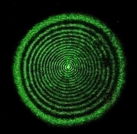
spinner using optical interference. I designed a laser
interferometer to produce interference by reflecting light
from a liquid while it is spinning in our mirror maker and
Art from the USC physics machine shop built the parts we
could not buy. The interferometer produced a circular
pattern similar to what is seen with Newton's rings. The
support of the spinning mirror is adjusted until the
interference pattern is radially symmetric with an
undistorted center. This approach is the same one used by
Borra to align the spinning for his mercury mirror
telescopes. |
|
|
|
|
|
|
Work on a
Two-Meter Spinning Mechanism
|
|
| From
2009 until 2012 I have worked on the setup of a two-meter
mirror spinner lab using the equipment Wally obtained with
a large grant from NASA. The equipment was installed in a
lab at lander College. The spinner consists of an
air-bearing with motor and controller, a steel plate to
support the epoxy containers, an oven enclosing the
spinning container of epoxy, a programmable temperature
controller for the oven and a compressor to supply air for
the bearing with nitrogen tanks for backup in the event of
compressor or power failure. The first batch of epoxy was poured in the fall of 2010. The initial production run of mirrors was for NASA’s JPL and the mirrors had diameters of 0.5 meters Their planed use is testing them as collectors for infrared laser space communications. JPL had hoped that some suitable 2-meter mirrors would be produced but as of the time I left the group, not a single acceptable 0.5-meter mirror was completed Below are some pictures from the work in that lab from 2009 through 2012. |
 |
|
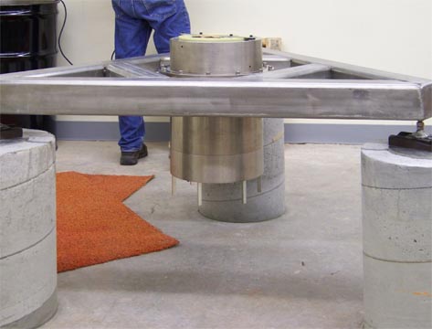
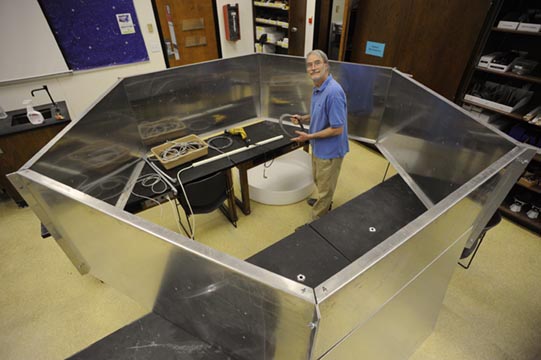
Air-Bearing
and Support Structure
Shown above is the installation of the air-bearing and stepper motor supported by the triangular frame used for leveling. This system can spin a metric ton load of epoxy with ease and precision. The air bearing needs a constant supply of conditioned, dry air even if it is idle or it becomes toast. Hence there is a bank of nitrogen cylinders arranged to automatically supply a flow of gas during power outages or a failure of the compressor. |
 |
|
Oven
Fabrication
Here I am inside the walls of the oven which will enclose
the spinner mechanism. The curing of the epoxy is
controlled by the temperature maintained in this even. The
oven heats the epoxy in order to fully cure it. Over the
summer of 2010 I moved the heater from the lab to
one of our physics classrooms so that it was easier for me
to finish its construction and wiring. This oven is now in service and has met most of its design specifications, though it does not yet have the ability to reach the glass transition temperature of the epoxy being cured. Prior to construction I modeled the heat flow in the oven and my calculations indicated the oven would need more insulation than called for in the original design (by a couple of chemists). My modeling of the heat transfer is very close to what was found in operation. Fortunately additional insulation is easy to add and I arranged the wiring and thermostatic controls so that the oven could operate at 220 volts rather than the current 110 volts and thus deliver four times the power to the heating cavity. |
 |
|
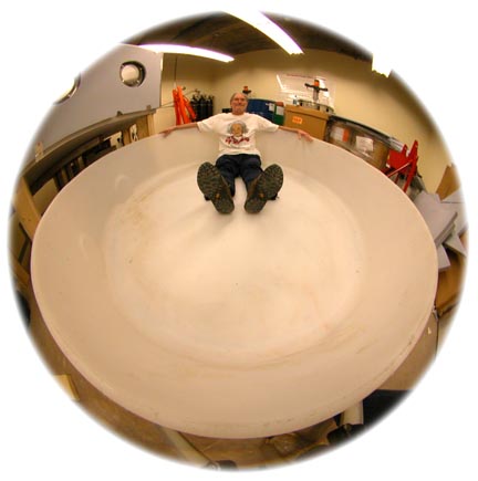
A
2-Meter Beaker Selfie
This is a silly picture showing me sitting in a 2-meter beaker next to the spinner and oven to be used to produce 2-meter mirrors, the size JPL needs. The idea was to use the beaker as the container for holding the epoxy on the spinner in the oven. Because the beaker is a polymer, it will sag in the oven so it remains to be seen how well this idea will work. I am no longer working with this group so I don't know if they ever got to this size. They were having major difficulties scaling their methods up to 0.5-meters. |
A Bigger Mirror Testing Lab at CofC
| In the
summer of 2011 the College moved my testing lab to a
larger location in the Lightsey Center. There I was able
to consolidate the equipment from two separate locations
and set up to spin some small mirrors. The
relocation has turned into a disaster. In the spring of
2012 some plumbing in the ceiling of the new lab leaked
water all over the testing equipment and has ruined many
optical and mechanical parts. In moving equipment out of
the way to deal with the water problems I discovered one
of the epoxy storage containers was cracked, most likely
in the move from the Bell building. Epoxy resin had
covered several square meters of the floor to a depth of a
centimeter or less. Clean up was slow in that the best
method for removing a thick liquid like that is to dust
the spill with a thick layer of sawdust and allow
capillary action to do it job. (Note: Using this same
approach with the hardener has a serious liability in
certain cases. The hardener reacts on the resin in the
wood releasing heat which can start ignite the wood and
lead to a serious fire.) After a week or so the layer of
goo is removed and the process repeated until no more
sawdust sticks to the floor. Then a swab with epoxy
thinner can remove the last of the residue. As of the fall of 2014 I was still rebuilding some of the equipment from this double whammy and expect to be testing again in the summer of 2015. I am no longer working with the chemists in the Lander College lab. I am rather certain they are at a dead end with the particular approach they have employed and they have encountered numerous problems, primarily with Physics 101 concepts that are impacting the final mirror figure. Now that I am working on my own, I can test several ideas for mirror production that I could not implement when someone else was calling the shots. The specifics of those ideas I will reserve for face to face conversation since the web crawlers can easily find this page and pass along a link to a Google search. But I will say I am working to manufacture a 20-centimeter (8-inch) mirror that will produce an image equal to or better than the photograph below while using the entire mirror. Up until now this result is yet to be superseded. |
||
 |
||
|
||